
Introduction
My son Alexey suggested making a tree out of LEDs to decorate the hallway. Naturally, it should blink. Well, dad thought and thought… We made it using ESP8266 (in the ESP-201 version), multi-colored LEDs, powerful transistors (obtained from fluorescent lamp ballasts), resistors, a couple of connectors from floppy disks. Alexey helped solder the LEDs, Nikolay was tasked with writing a program in the Arduino environment, with a simple web page for uploading new “melodies”.
Hardware
First, my child and I sketched out a picture of a Christmas tree and presents on a piece of paper. We sketched out a rough version of the power bus layout. Due to the chosen connection scheme (see below), the common bus is +5V (not ground).
Attention! Different LEDs have different voltage drops and are designed for different maximum currents. The easiest way to limit the current through an LED is to use a resistor. Since our supply voltage for the LEDs was about 5.4 volts, it was possible to pair some LEDs (with < 2.5 volts) in series. This increases the efficiency of the circuit (less energy is dissipated on the resistor). You can use online calculators to calculate resistances.
For the base, we cut out cardboard from a pizza box.
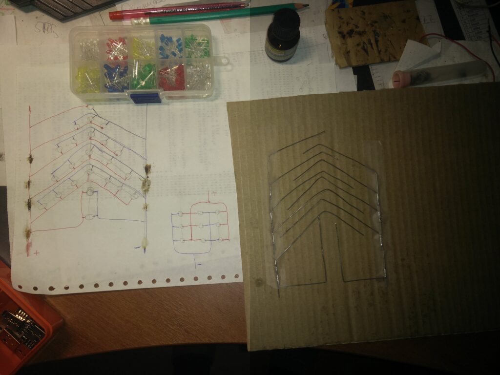
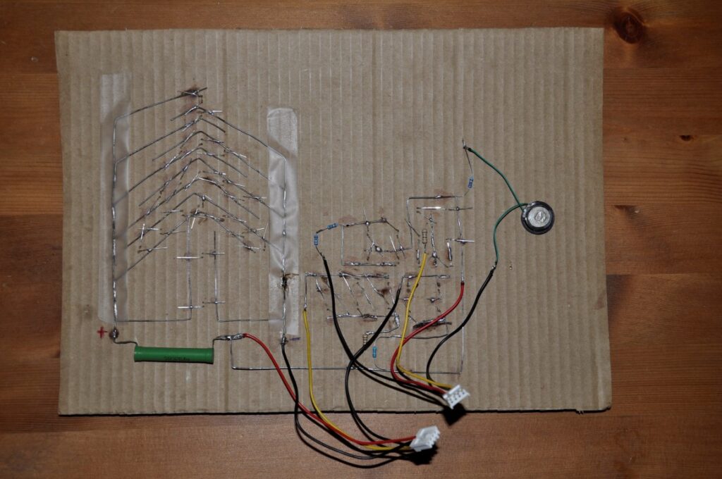
To solder the LED legs to the iron wire, we used flux, without which it is difficult to solder. The calculated resistances were soldered directly to the LED blocks. It turned out a bit clumsy, but fast and clear. To make the design modular, i.e. so that the “display” could be disconnected from the board, individual elements were soldered to connectors from floppy disk drives, cut from the computer power supply cable.
The ESP8266, purchased in the ESP-201 version, is used for control. (For those who do not know what ESP8266 is, you can look here. Roughly speaking, it is an Arduino with built-in Wi-Fi. ESP-201 modules can be purchased on Aliexpress for ~150 rubles). Of course, the ESP8266 cannot directly power such powerful loads, so I used NPN transistors connected according to the scheme with a common emitter. Below is a schematic diagram (for three groups of LEDs). Resistors R1-R3 are needed for the controller itself to work, R4-R6 to limit the current at the controller outputs through the transistor bases, R7-R9 to limit the current on the LEDs. The ratings of the latter are not indicated, since they depend on the number, characteristics and connection scheme of the LEDs (see the online calculator above). In principle, R1-R6 can be selected in a wide range (1k – 20k). If the values are too small, the controller can be burned out, if too large, the transistor will not open. I unsoldered the transistors from ballasts for fluorescent lamps (available due to a planned replacement of lighting) and an old computer power supply.

At first I was going to solder the circuit on a breadboard for soldering, but it didn’t work the first time. And since time was running out, I used a breadboard with sockets. I soldered three-pin connectors to the transistors.

Caution! Transistors must not touch each other with their housings.
To convert 5 Volts to 3.3 Volts, which is necessary for the controller, I used a ready-made miniature converter. It supports current up to 800 mA, which is enough for the controller.
The main power supply is a charger from some defunct gadget, which produces 5.4 Volts at 1.850 Amperes. I used a power connector similar to those used in many toys for charging batteries. For on/off – a micro switch.
Here are pictures of the components used:


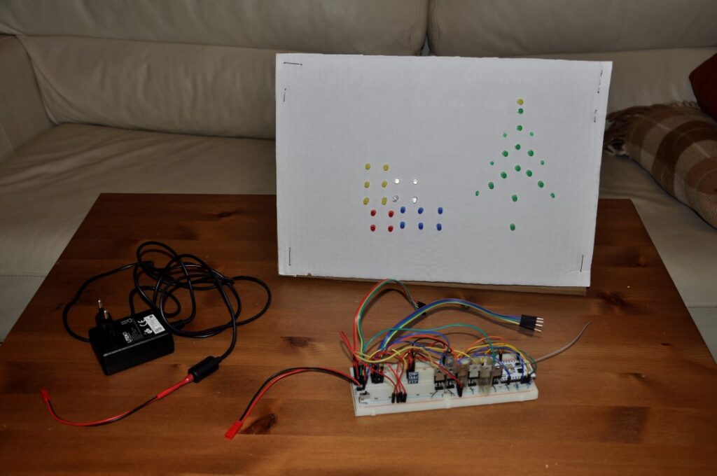
For the final assembly of the “display”, I covered the back with a second piece of cardboard and made a stand using wire “legs”. The breadboard is placed underneath and at the same time makes the construction more stable.

Software
The Arduino environment configured for ESP8266 was used for programming. More details on GitHub. The program is based on the example of a standard web server. It parses POST from the form and, based on the argument value, in a cycle, it sets the controller’s digital outputs. The controller is connected to a home Wi-Fi network and the system can be configured from any computer or smartphone.

Kolya came up with a long “melody” that has been left for now. The video is on Facebook.
Leave a Reply
You must be logged in to post a comment.