
Tired of constantly adjusting the time on the table clock in the bedroom. Perhaps the most important clock in the apartment was constantly running out and even reset when the power went out.
I decided to make my own clock, connected to the network via Wi-Fi and receiving time via NTP.
Hardware
As a control module, I chose ESP8266, for which I already had a customized Arduino IDE and some development experience.
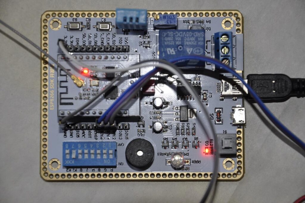
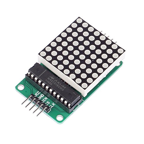
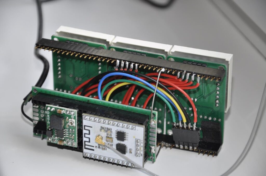
For development and debugging, I used a convenient SDK board for ESP8266. Several 8*8 LED matrices were available. I was going to play with them with my children, so I ordered some extra. The matrices use the MAX7219 chip to control the LEDs. Information is transmitted sequentially, and it is possible to connect several modules in series. There are many libraries for such matrices on the Internet, including those with ready-made fonts. But for this project, I made my own font, which is better suited for watches. Below is an assembly of three matrices connected in series.
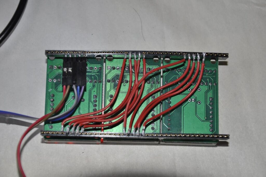
I used detachable connections between the main modules to make assembly/disassembly and replacement of parts easier.
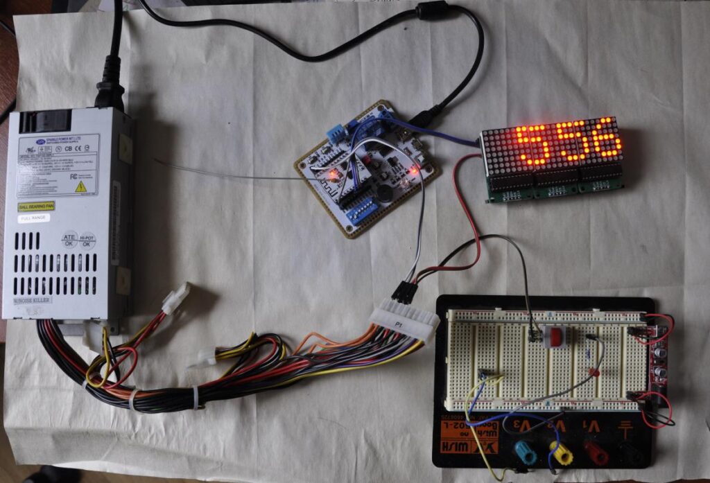
This is what the entire stand looked like. The power supply was computer power, it had the necessary 3 and 5 volts with some extra power. The three matrices, when fully turned on, consume a decent amount of current, and won’t work from a computer USB port.
Software
The program is quite simple. I already had ready examples: working with LED matrices for Arduino, and sending a request / parsing an NTP response for ESP8266. All that was left was to merge this into one working program and add a few things:
- Connecting to my home Wi-Fi network, + reconnecting if something doesn’t work. Likewise, several NTP servers, queried in a circle.
- Since the ESP8266 has no internal clock, then setting up delays for satisfactory accuracy of autonomous running for ~15 minutes, after which a new NTP request is made.
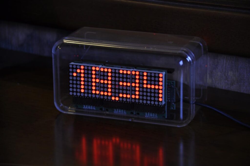
- New font (only numbers), maximizing the use of the screen and visible to nearsighted people from several meters away.
- Some additional indication in the bottom line (is there a connection to the network, etc.)
Prototype
After creating the software and normal operation of the device on the stand, I moved on to creating a more portable power supply for the prototype itself. To get 5 Volts, I used a charger from a mobile phone with a damaged mini-USB connector. LED matrices are powered directly from 5 Volts, and for the operation of the ESP module, a custom DC-DC converter to 3.3 Volts was used.
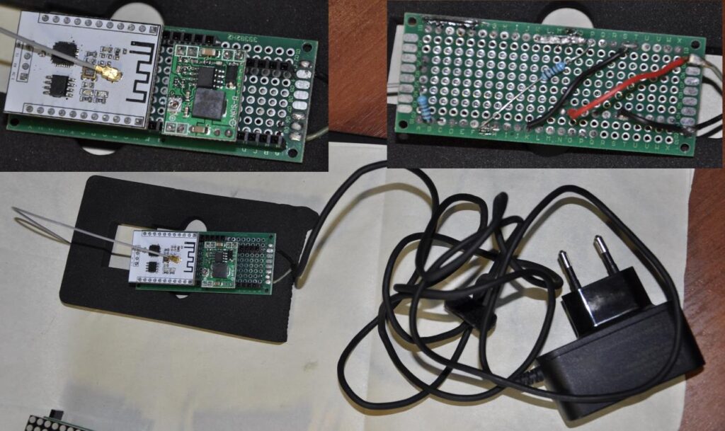
I connected the assemblies together with a rigid wire, simply soldered to the breadboard. I had an idea to print some kind of frame on a 3D printer, but I never got around to it. The final look:
All together it fits perfectly into a candy box that has been carefully stored for several years:
Conclusion
Of course, this was a short summary of the story. In reality, I had to redesign the device a couple of times, wrestle a bit with Wi-Fi, and write off one DC-DC converter, from which all the magical blue smoke it worked came out.
But it turned out very nice:
P.S.
In principle, the idea has great potential, because it costs practically nothing to add an indicator for, for example, new mail, the weather in a running line, the state of the entrusted servers, whatever. Maybe it will be possible to force the child to develop the system 🙂
Leave a Reply
You must be logged in to post a comment.