The project was conceived for joint work with my children: Nikolai (12 years old) and Alexey (8 years old). In an attempt to interest the children in something educational, I bought Strela (Arduino Leonardo) and RaspberryPi B+ boards for experiments.
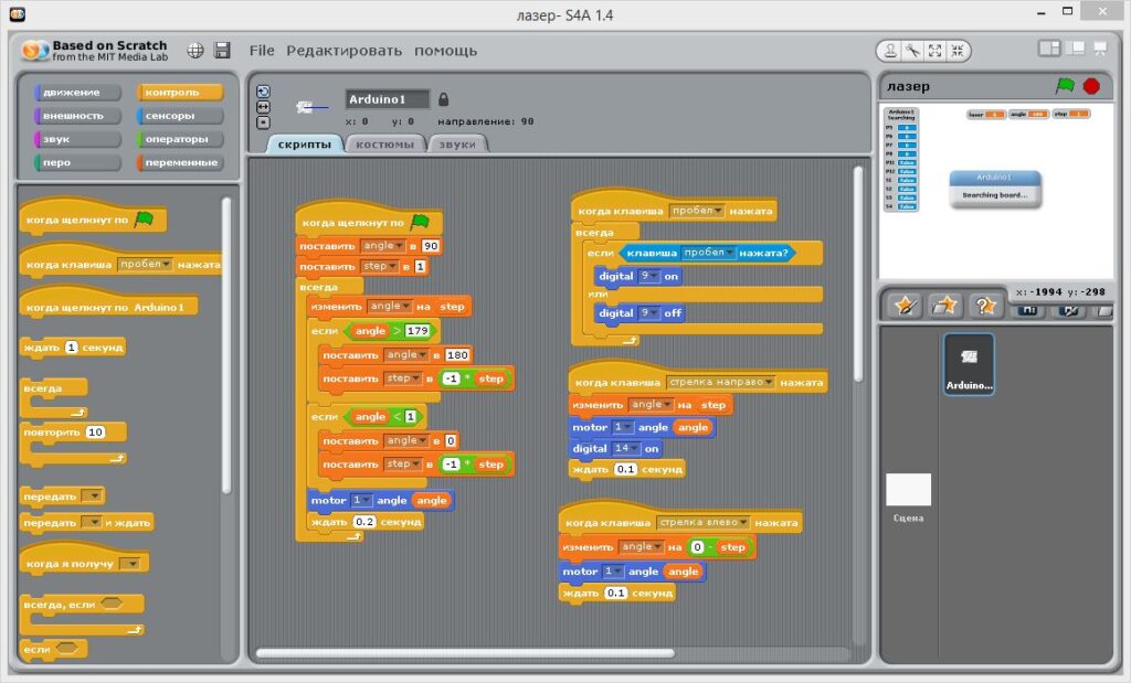
After some torment, Strela was able to befriend the children’s Scratch development environment. (The torment consisted of modifying the communication protocol in Scratch 1.4 (made in Squeak Smalltalk). On the Arduino side, it’s just C, so everything is much simpler.)
We made a couple of interesting projects, for example, a radar from a servo drive and an ultrasonic distance sensor. With the younger one, we wrote a program in Scratch to rotate the sensor in a 180-degree sector, with the older one, we received data on the distance to the obstacle and the current angle over the network on his computer. Then we drew on a pie chart. We did it in PascalABC.NET, they use it at school.
But, of course, all this became uninteresting when the children saw numerous mobile robots based on Arduino on the Internet.
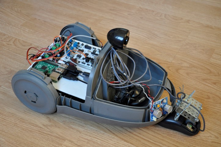
While I was thinking of how to approach this without much capital investment, our vacuum cleaner burned out 🙂 Well, I took it apart, there was some kind of nonsense inside (c). The engine, which is what it actually consists of, broke down. After dismantling the engine, there was an excellent body left, which had survived years of brutal use, with two wheels in the back and one swivel roller in front. So we got a platform for our prototype. And this is what came out:

Control
I used both boards. The Strela is responsible for the basic “real time” functions. Synchronous control of motors, response to sensors.
The Raspberry is responsible for the “high level” functions. Wi-Fi connection to the home network, the “Remote Sensors Protocol” server for integration with Scratch via TCP/IP, a small WWW server for an alternative control channel, a video server. The boards communicate with each other via a serial USB port, using a simple homemade text protocol. For the Raspberry, everything is written in Python, except for the video server, it is ready-made.
Platform
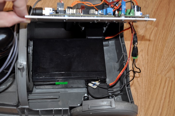
All printed circuit boards are screwed to a common panel. Underneath it is a 12V lead-acid battery from the UPS, and two constant-speed servo motors.
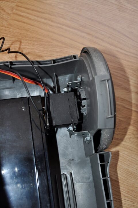
The motors are secured with curved parts from a children’s construction set (this is where a 3D printer would come in handy!). The rotation is transmitted to the wheels via plastic “stars” that came with the motor. For them, cuts were made in the vacuum cleaner wheels. Servo motors were chosen because of their high torque, while high speed is not needed, the diameter of the wheels is large enough.
Power supply
Voltage from the 12V battery is supplied in parallel to three devices. To the Strela board, which has its own voltage stabilizer. To the DC-DC converter for converting to 5V to power the Raspberry. And to the DC-DC converter to 7V to power the motors. In principle, the motors and Raspberry could be powered from one converter, but I was afraid of voltage drop at startup or due to blocking of the motors and, as a result, rebooting the Raspberry. The resulting circuit is resistant to voltage drop on the battery to 7V.
The power button is taken from the vacuum cleaner itself. A wonderful thing, it worked for many years, switching a kilowatt load, and nothing happened.

Additional sensors
The Strela has a lot of digital and analog inputs and outputs, as well as four buttons and four LEDs on board. So there is a lot of potential for development. So far, I have only connected an ultrasonic sensor to the analog input. It allows the robot to stop in front of an obstacle without crashing into it.
RaspberryPi B+ has four USB ports. In addition to the Strela and Wi-Fi adapter, I connected a webcam and a mouse.
The camera uses the standard motion package, thanks to which the image from the camera can be viewed in a regular browser from any computer in the apartment. Unfortunately, there is a decent delay and this service loads Raspberry by about 25%. But still, remotely controlling the robot and receiving a picture from it is really cool 🙂
The mouse was an attempt to create a motion sensor. It turned out that in Python it is quite easy to read coordinates from a USB mouse, wheel rotation and button presses. The plan was to create a map of the robot’s movements and draw it on a remote computer.

Unfortunately, I can’t say that not a single mouse was harmed in this experiment. But the Microsoft inscription on the mouse significantly eased my moral suffering when drilling a hole and breaking off buttons 🙂
In principle, the idea works, but two problems were discovered:
- for the mouse sensor to work correctly, it needs to be close to the surface. Refocusing the sensor to a greater distance did not work. I only had a couple of lenses at hand, and they did not fit. As a temporary solution, I assembled a unit for a movable mouse mount. It allows the mouse to slide along the floor and rise up. So the robot can run into small obstacles like a carpet or threshold.
- to fully determine the position of the robot on the plane, you need to know two points (=mouse). With just one, even located in front, it is not possible to accurately build a trajectory. When turning, the wheels slip, and it is impossible to accurately determine the point around which the body turns even on a flat surface. Well, the geometry here is already too complicated for the 6th grade.
Leave a Reply
You must be logged in to post a comment.